Education
This section contains information on multibeam sonar to meet all educational levels. Informative videos that provide an elementary introduction to mapping the seafloor are supplemented with an in-depth tertiary level description of multibeam mapping. Links to other information can be found at the bottom of the page.
Multibeam mapping
Synonyms: Multibeam sonar mapping, Swath Mapping
A technology used for detailed 3D mapping of the seabed utilising a vessel-mounted multibeam sonar that transmits a fan, or swathe, of acoustic energy across the ship track; then resolves multiple depth points across the swathe based upon the slant range and elevation angle of reflected echoes from the seafloor. Lidar is a similar technology to multibeam but using airborne laser bathymetry to swathe map shallow clear waters.
Multibeam sonar
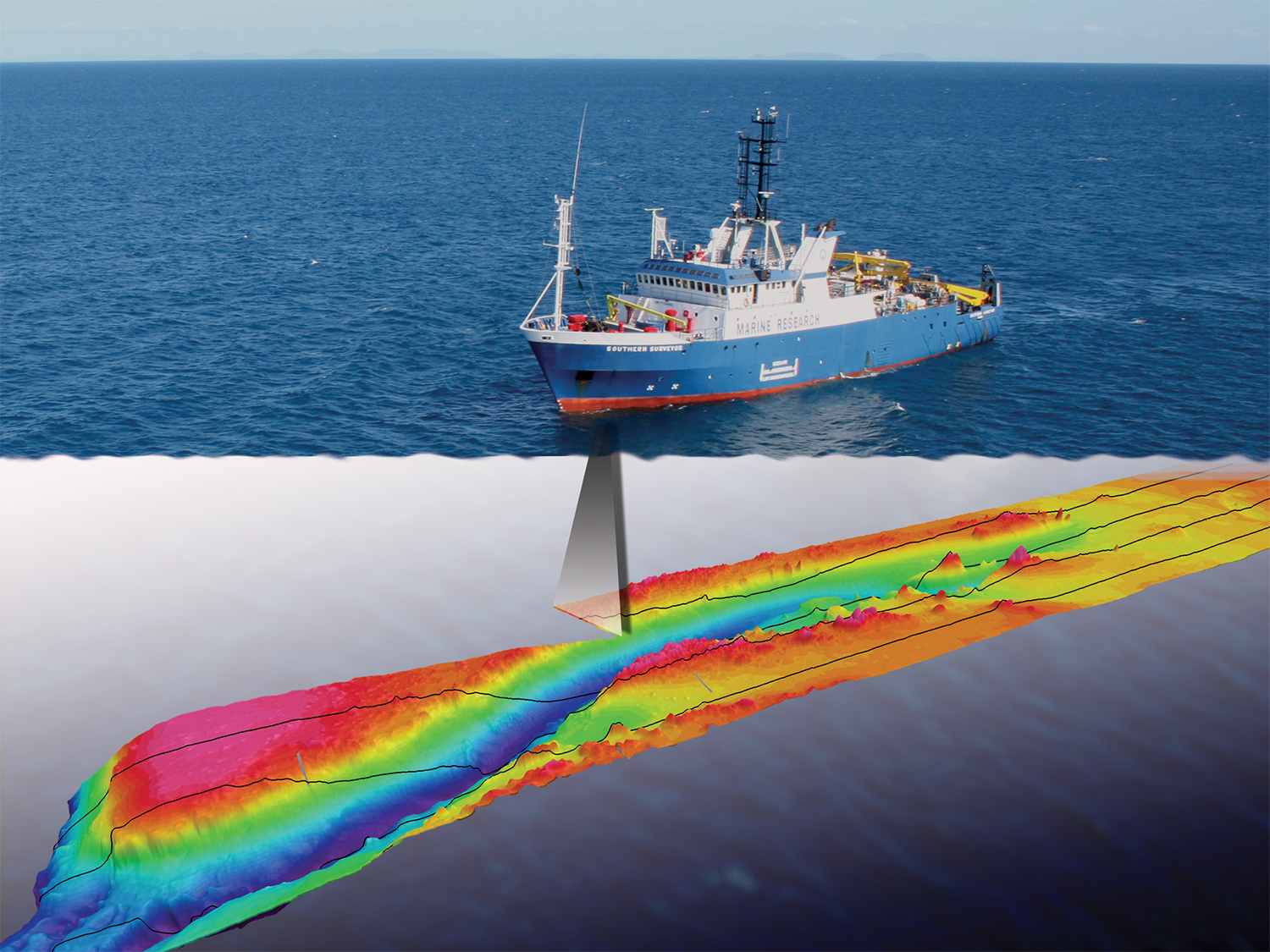
Composite image showing the 3D effect of swathe mapping an ancient river channel incised into the Great Barrier Reef shelf, Australia, using a vessel-mounted multibeam sonar system. Grid pixel resolution is 5 m. Total grid distance is about 8 km. Photo credit: Rob Beaman
Singlebeam echosounders have been applied routinely for many years to collect bathymetric or depth data from the world's oceans. This acoustic technique relies on a vessel-mounted transducer to generate a single acoustic pulse directed towards the seabed underneath the vessel. The echosounder then calculates a depth measurement based upon the speed of sound through water and the travel time for the reflected seafloor echo to return to the receiver. During the 1970s, development began on multibeam sonar systems that use a multi-element transducer array to transmit a fan, or swathe, of acoustic energy across the vessel's track. The swathe is narrow in the along-track direction, typically 1-2 degrees, and wide in the across-track direction, generally 120 degrees or more. The transmitted acoustic pulse frequency ranges from higher frequencies up to 450 kHz for mapping shallow coastal waters and the continental shelf, down to lower frequencies of 12 kHz for mapping the deep abyssal sea floor.
The multibeam receiver array measures the slant range and elevation angle of multiple seafloor echo returns across the swathe, and usually the echo strength of the returns which is called backscatter or amplitude. The multibeam sonar system also tracks the precise position of the vessel and motion data, such as gyro heading, heave, pitch and roll, to calculate an accurate depth and position for the individual depth soundings. The number of depth measurements across the swathe varies between instruments but can be 100s to 1000s of soundings per second. As long as the vessel is moving forward relative to the seabed, a multibeam swathe survey results in a dense 'point cloud' of soundings that can be used to generate a 3D depth model which accurately maps the underwater landscape. The resolution of seabed features that can be detected in such depth models can be sub-metre in size for shallow waters. However in deeper waters, the resolution of observed features reduces to tens of metres due to the spreading properties of acoustic energy over longer distances and the lower frequencies used to ensonify the sea floor.
Lidar
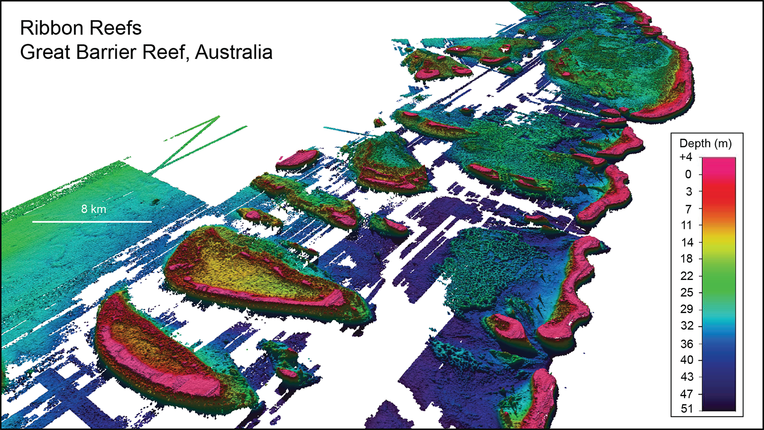
Lidar mapped Ribbon Reefs in the northern Great Barrier Reef, Australia. The gaps in data coverage are inter-reefal areas where seabed depths lie greater than about 50 m, the limits of laser penetration into the water column. Grid pixel resolution is 25 m. Total grid distance is about 110 km. Photo credit: Rob Beaman
A similar seafloor mapping technique to multibeam sonar is the use of airborne laser bathymetry, or Light Detection and Ranging (lidar), which use low-flying aircraft to scan pulsed laser beams across the seafloor and generate a swathe of depth soundings. For example, the Laser Airborne Depth Sounder (LADS) uses a narrow infrared (1064 nm) beam fired directly at the sea surface beneath the aircraft but does not penetrate the water, and thus reflects directly back to aircraft for calculating the aircraft's height above the water. A scanning mirror reflects a second green (532 nm) laser that tracks back and forth across the flight path in a grid pattern. The scanned green laser penetrates the water column to a limit of about 50-70 m (in clear water) that reflects off the seabed, if lying within this depth limit. The airborne receiver detects any reflected green laser signals and converts the returned signals into multiple depth points after subtracting the aircraft height value obtained from the infrared laser.
Data density and acquisition rates vary between lidar instruments but typically collect about 1000 depth soundings per second, with a swathe width of 200 m while flying at a height of about 500 m. At this height, the green laser beam footprint at the sea surface is about 2 m while the actual grid spacing can vary from 2-10 m apart. With aircraft speeds of about 150-175 kn, lidar can deliver fast, high-resolution, shallow water surveying capabilities compared to vessel-mounted multibeam sonar systems. The major disadvantage of lidar compared to multibeam is that laser signals are highly attenuated in turbid water and therefore lidar is ideally suited for surveying only in clear shallow waters. However, tropical coral reef areas provide additional navigational dangers to vessels conducting multibeam surveys, and so lidar has been used to successfully map large areas of continental shelf where vessel surveys would be impracticable.
Examples
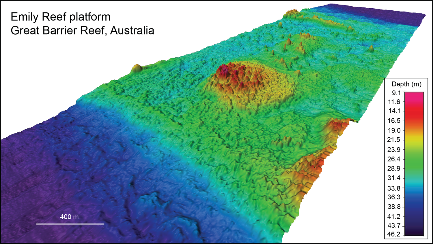
An example of a multibeam swathe mapping survey over Emily Reef, a broad coral reef platform on the northern Great Barrier Reef, Australia. Grid pixel resolution is 5 m. Total grid distance is about 8 km. Photo credit: Rob Beaman
The development of the various swathe mapping technologies represents an evolution in the ability to image large areas of the seafloor in nearly as high a detail as found in aerial photographs of land. For state mapping agencies, these advanced technology mapping tools provide the density of soundings to detect fine-scale shoal features that pose risks to maritime navigational safety (see Australian Hydrographic Service). For industrial and scientific purposes, this evolution in ocean mapping technology reveals the true shape and geological nature of the seafloor. For coral reef environments, swathe mapping has provided new insights about the geomorphology of coral reefs and the inter-reefal seafloor beyond the limits of scuba diving. Combined with other remote sensing techniques, such as sub-bottom profilers and towed sidescan sonar, and optical and sediment ground-truth methods, the detailed seabed habitat maps are a fundamental first step on which to base management decisions about coral reef ecosystems (see Pacific Islands Benthic Habitat Mapping Center).
The Future
Future improvements in swathe mapping technology will increasingly see multibeam sonar systems mounted on underwater vessels, such as remote operated vehicles (ROVs) and untethered autonomous underwater vehicles (AUVs). The advantage of taking a multibeam system closer to the seafloor are improvements in the quality of acoustic returns, but these methods also provide engineering challenges for the accurate positioning and orientation of the vessel within the water column. Other mapping advances will see greater use of multi-frequency (hyperspectral) acoustic and laser transmissions which allow improved generation of co-registered seafloor reflectance (substrate) imagery, as well as mid-water feature detection, such as schools of fish and gas seeps. There will also see advances in the development of interactive 3D visualisation software in order to facilitate the interpretation and analysis of these large, complex, multi-component spatial datasets.
Conclusion
Seabed mapping techniques, such as multibeam and lidar, have provided an evolution in mapping of the world's oceans over the past few decades. For tropical coral reefs, mapping provides greater understanding about the true nature of the deeper seabed and inter-reefal habitats. These new discoveries are guiding major advances in energy extraction, fisheries resource management, and environmental protection of the sea.
Robin J. Beaman